Zachtkind connects to ByronStatics KCS-315. There are two versions, they have the same name and look the same, but are different from the inside. For walkmans ordered before 2022 you will probably have to use these instructions .
There are 3 pcb's, thin red one is a cover for the rotary potmeters (in the new kit all PCB's are black). The black one is a spacer for the 4 tactile switches. The big red one is is the main circuit PCB.
When soldering the PCB make sure the components are cut off as close as possible to the PCB. Because it will be stuck to the walkman with a double sided tape. It helps to cut the legs before you solder them.
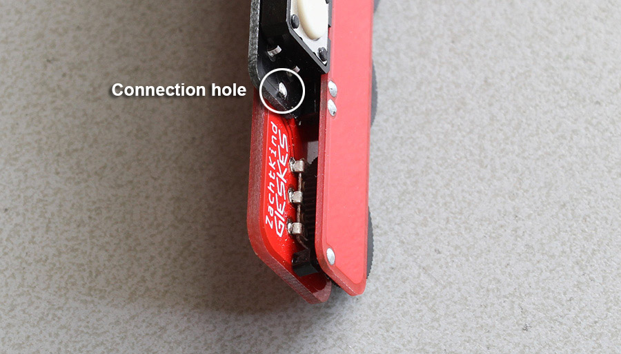
Black spacer PCB for the switches, you can use 1 second glue to stick it to the maine red PCB. Put in the switches and solder them. make sure the connection hole lines up, without this connection soldered It will not work. You can use a leg from the resistor to make this connection.
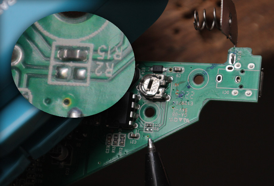
Solder all the small components, switch, jack socket, resistor (68k, says 47k on PCB), diode (small red/transparent 5v1, has polarity).
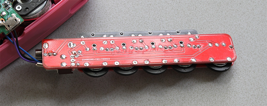
Solder the potmeters flat on the main PCB (1x10k says B103 on potmeter, 4x50k says B503 on potmeter).
Put the 2 pin headers into the main PCB, and the 1 pin headers also.
Put the pot cover PCB on them (pins thru holes) and cut of the pins that stick thru so it aligns flat with the cover PCB.
Make sure its all strait, then solder the right single pin first then the left single pin.
Check if it is all stil strait and solder the rest of the pins.
Clean of the solder flux if there is any.
Put a peace of news paper (thin paper) between the potcover and the pots, cut off pins that stick out to much and solder it to the main PCB.


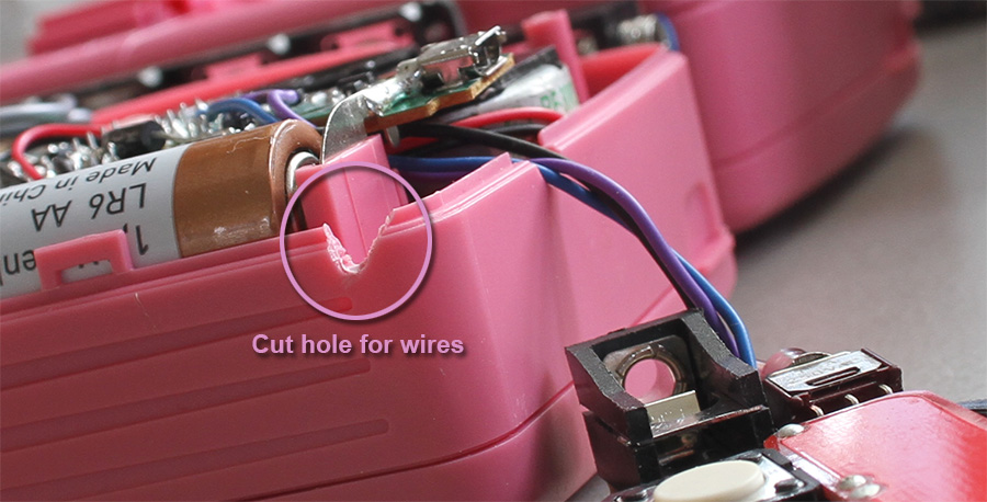
Cut a hole for the wires.
Use TESA POWERBOND INDOOR 19mm double sided tape to stick PCB to walkman.
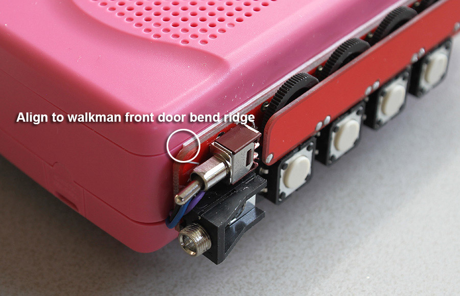
When sticking the PCB to the walkman align it to the cover so it can still bend open.

FINISHED!

Below are detail pictures to help with assembling.

