?Man+ connects to the BaseTech KW-118C Walkman.
(probably the same walkman as the: Renkforce RF-CP-150 and the Roxx PCP 300).
Put one in each corner, this way it will lay flat on the surface when laying on its front door.

Remove resistor R3 by putting solder on the soldering iron and holding the solder to the resistor, it will come loose and stick to the solder. (in the above picture the resistor is already removed).
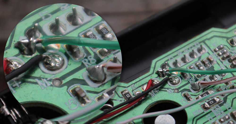

The blue and brown wire can be soldered as the picture above.

The White wire with Green line can be soldered as the picture above.
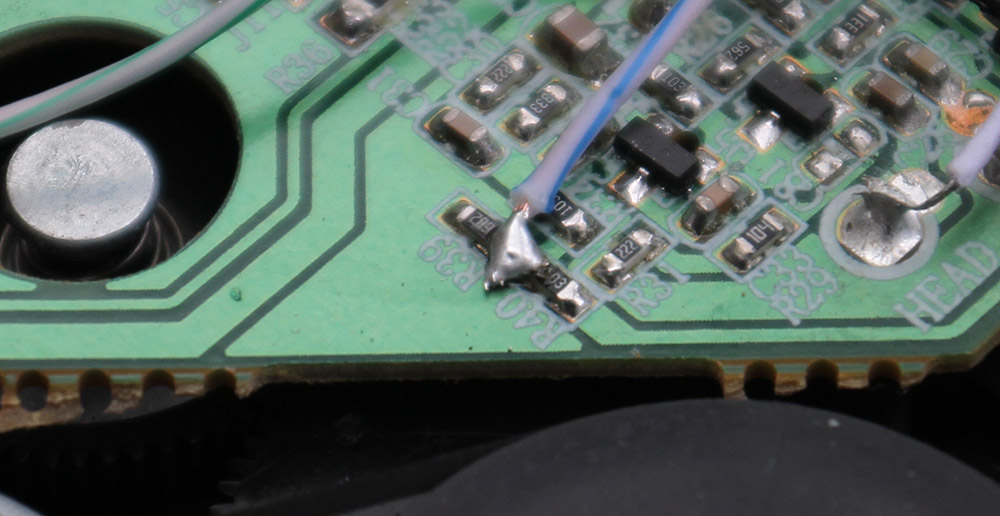
The White wire with Blue line can be soldered as the picture above, in between R40 and R39.
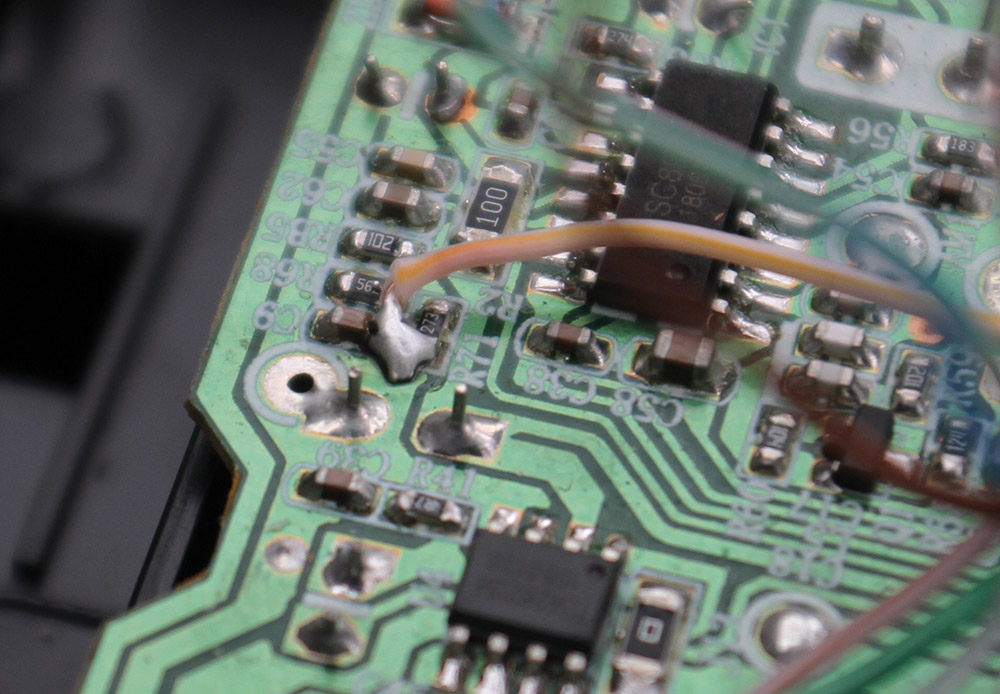
The White wire with Orange line can be soldered as the picture above, in between C9 and R71.
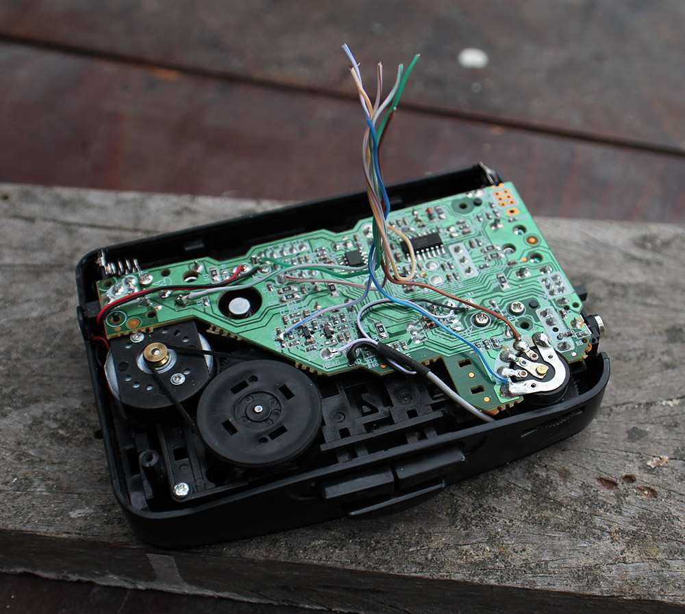
You can roll up the wires a bit this way they go thru the hole in the back pannel and the PCB more easily.
The wiring and modifications to the walkman are done now, the rest is easier.

Remove the belt clip and cut of the Belt clip holder things, that stick out. I used a strong flat wire cutter. This is to get a flat surface for the PCB to be sticket to the walkman.

Drill a hole in the back panel in similar size as the hold in the middle of the PCB.
Before drilling place the PCB over the back panel in the same place as the above picture and mark the place where to drill on the back pannel with a pen (or smth).
The place of the PCB is important because the inductor picks up the magnetic field from the motor of the walkman, if you pit the PCB in another place, it will not pick up the motor sound.

Start with the smalles components first an then move up to the bigger components.
make sure the slide potmeter can still fit into its place next to the blue trimmer pots (1m, 200k, 50k).
After soldering everything cut of the legs that stick out longer the 1 mm from the bottom of the PCB, to help the 2mm double sided tape stick the ?Man+ PCB to the walkman good.

When soldering the big buttons you can push the whit caps on them first, then you can us them to visually align the side with the side on the walkman so they are strait. Then solder one pin, check if they are strait and flat on the PCB, then solder the other pin.

Add this mod, it will reduce hum allot for when you touch the potentiometers, all three of them. Basically we ground the chassis of the potmeters thru 20k resistors.
Stick the double sided tape to the bottom of the ?Man+ PCB, but dont stick it to the walkman yet. First we need to solder the wires.
Cut the wires to legth (no need to cut allot off, can also cut nothing off), Strip the wires and tin them, then solder them to the ?Man+ PCB.
Now is a good time to check if the ?Man+ works good, before sticking it to the walkman.

Now stick the PCB to the Walkman with the double sided tape in the correct place, you only get one try to stick it good. Stick it to the same place as i the above image.
You can now push the wires into the hole in the PCB and under the slide potentiometer.
