These are the old instructions, they are still relevant to check out for this kit also.
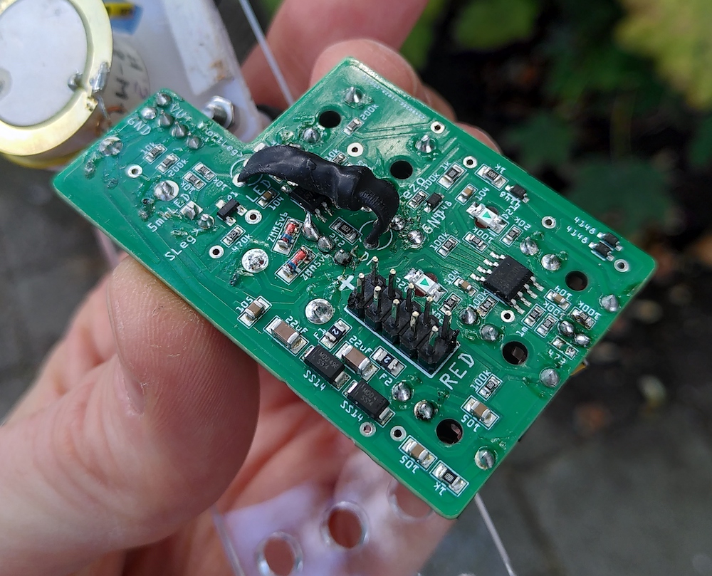
Solder the bottom side of the PCB first, the 2x5 pin header and Vactrol.
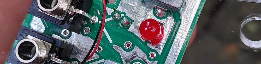
Solder the red LED, on bottom side it is marked 'SLeg>' (Short Leg). Short leg into round hole.
Cut of the flap of the pot that goes to the fornt pannel (there is no hole for it in the front pannel).
After soldering the red LED you can put all the jacks and pots in there holes, and mount the PCB to the front pannel. The 200k pot has no nut, it goes into the place in the middle of the PCB (check the front pannel if your not sure, because the shaft is smaller so the hole is smaller).
Then when it is mounted, you can solder the pots and jacks. (please keep the temperature of te iron below 300 degrees on the wiper pins of the pots) .
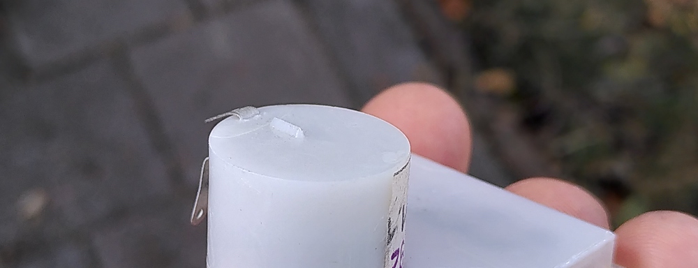
Cut the white little plastic bumper off of the vu meter (this is where you have to stick the piezo to with the foam tape, better if it is flat)
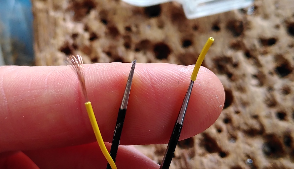
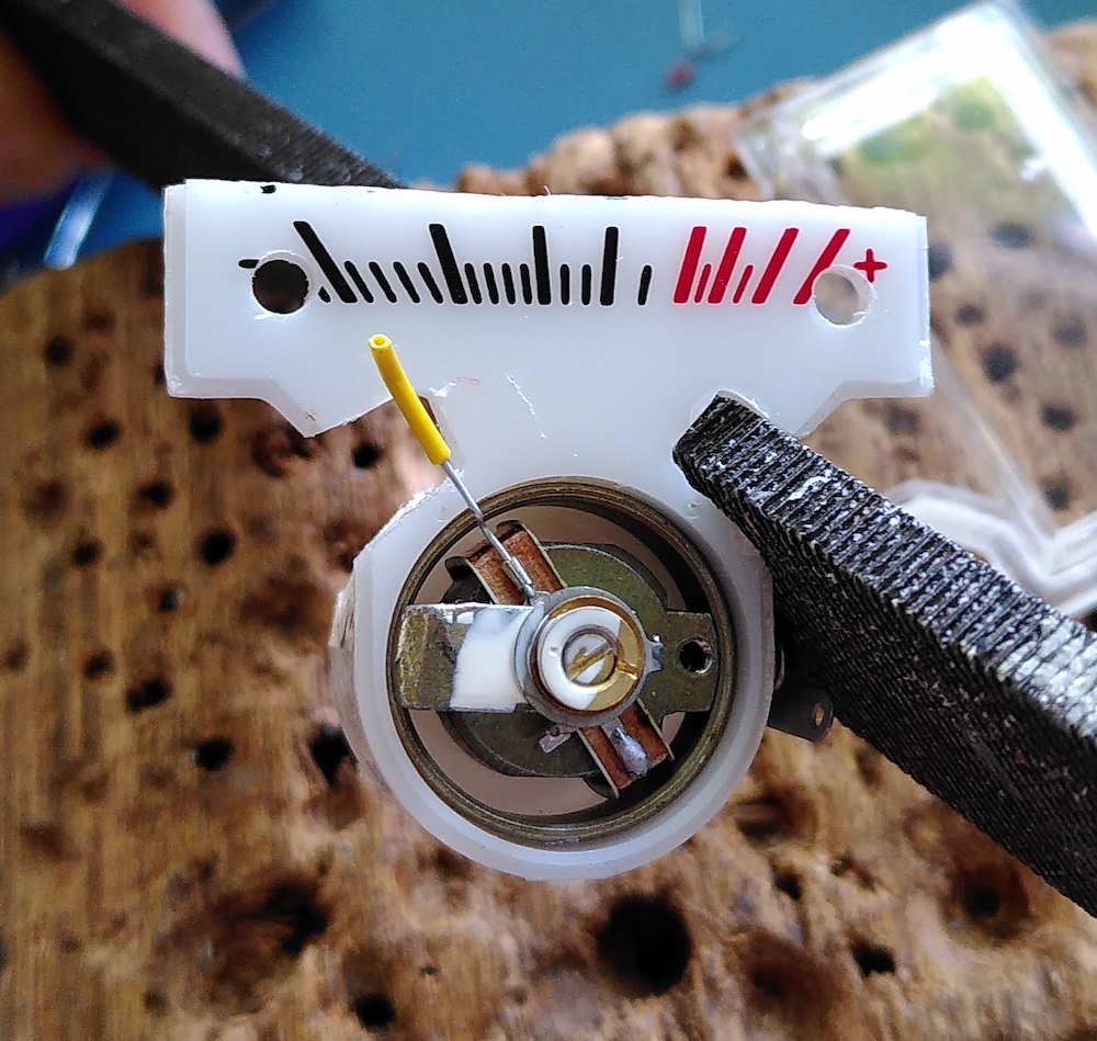
Slide a bit of the sleave of of the wire, and stick it on the end of small tweezers to make the inside bigger.
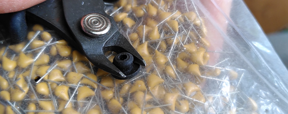
Cut the rubber bumpers shorter.
Cut the plastic transparent cover of of the vu meter and trimm it smaller with a big flat cutter.
Drill M3 holes into the vu meter for mounting.
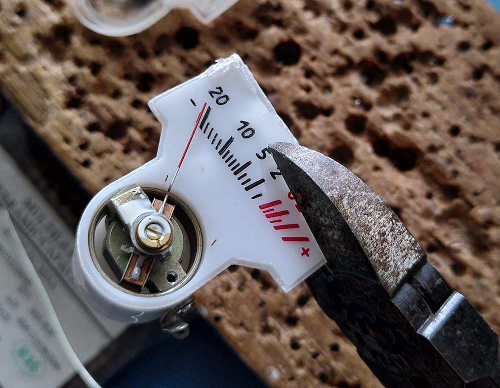
Cut the vu meters wiper a bit shorter, then slide the tube sleave over it and bent it a bit so it stays in the same place.
Use a file to make hole in the side of the vu meter (dont use cutters for this because it will break the plastic in two peaces).
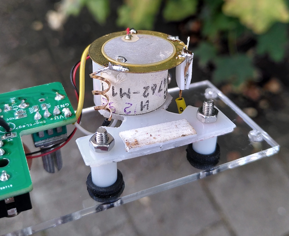
Stick the piezo to the vu meter with the foam tape.
Solder the sound making parts and get creative there.
Mount the vu meter to the front pannel with the rubber bumpers, bolts, spacers and nuts.
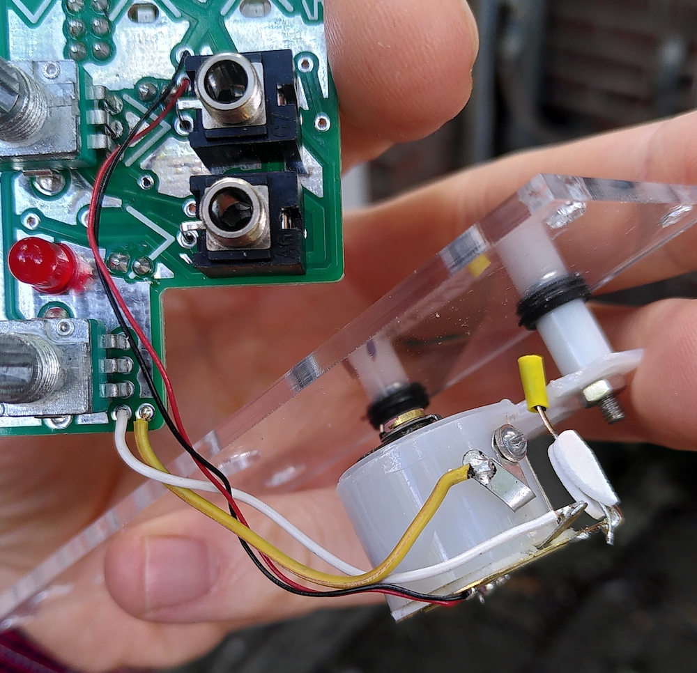
Connect the wires.