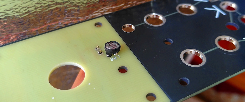
Solder the LDR onto the top panel, and the 2 pin header also.
You can slide the 4.5mm shrink tube over the LDR then when you solder it to the PCB
it will shrink because the LDR warms up from soldering its pins to the PCB front panel.
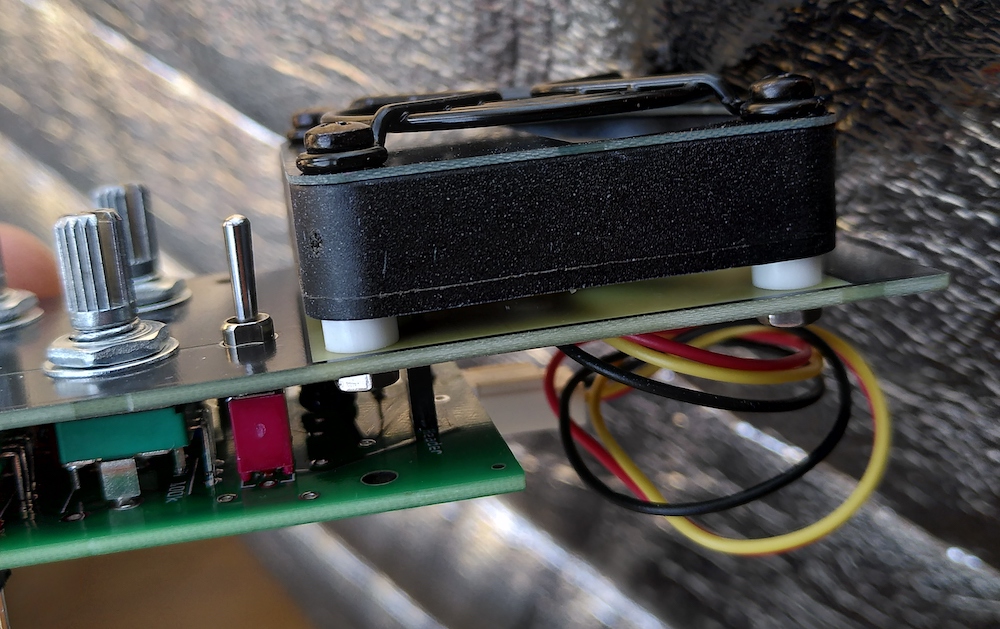
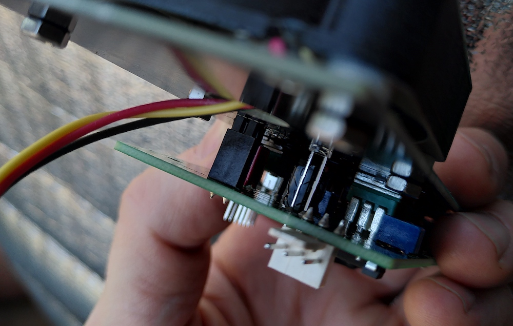
Screw the fan to the front pannel with the bolts, see picture above for how to. Dont forget to put the fans cable thru the big hole in the front pannel under the fan.
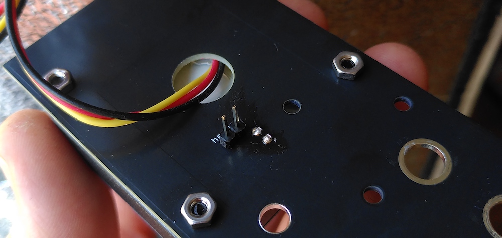
Fan cable going thru hole.
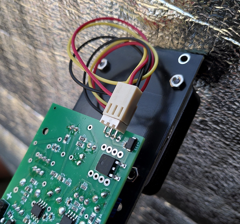
Solder the power connector for the FAN to the PCB. It can also be on the other side of the PCB.
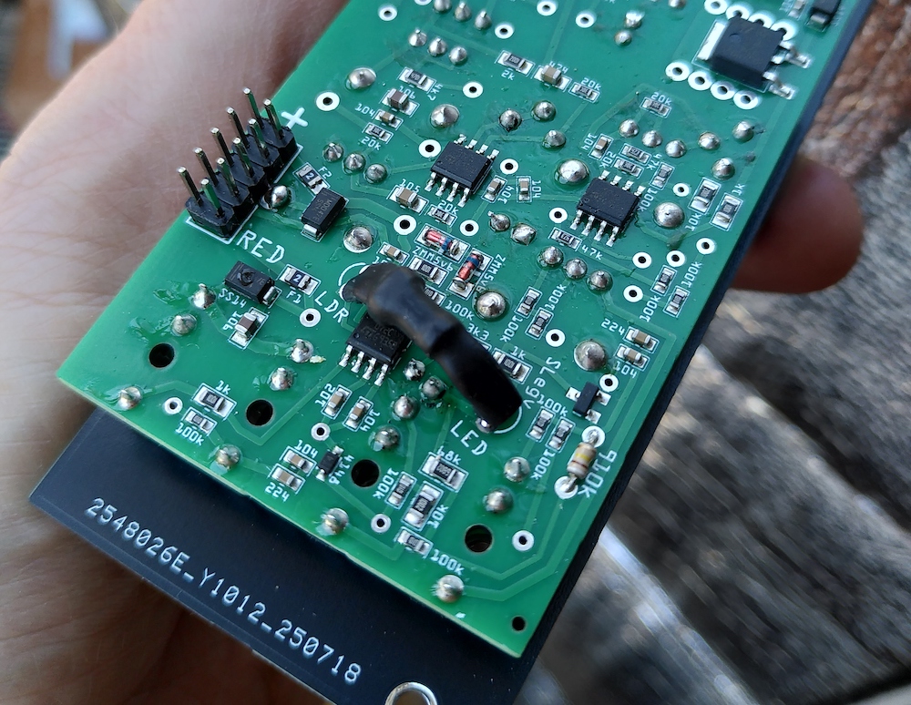
Solder the VACTROL, the power connector and the 910k resistor (910k resistor is on the right of the VACTROL).
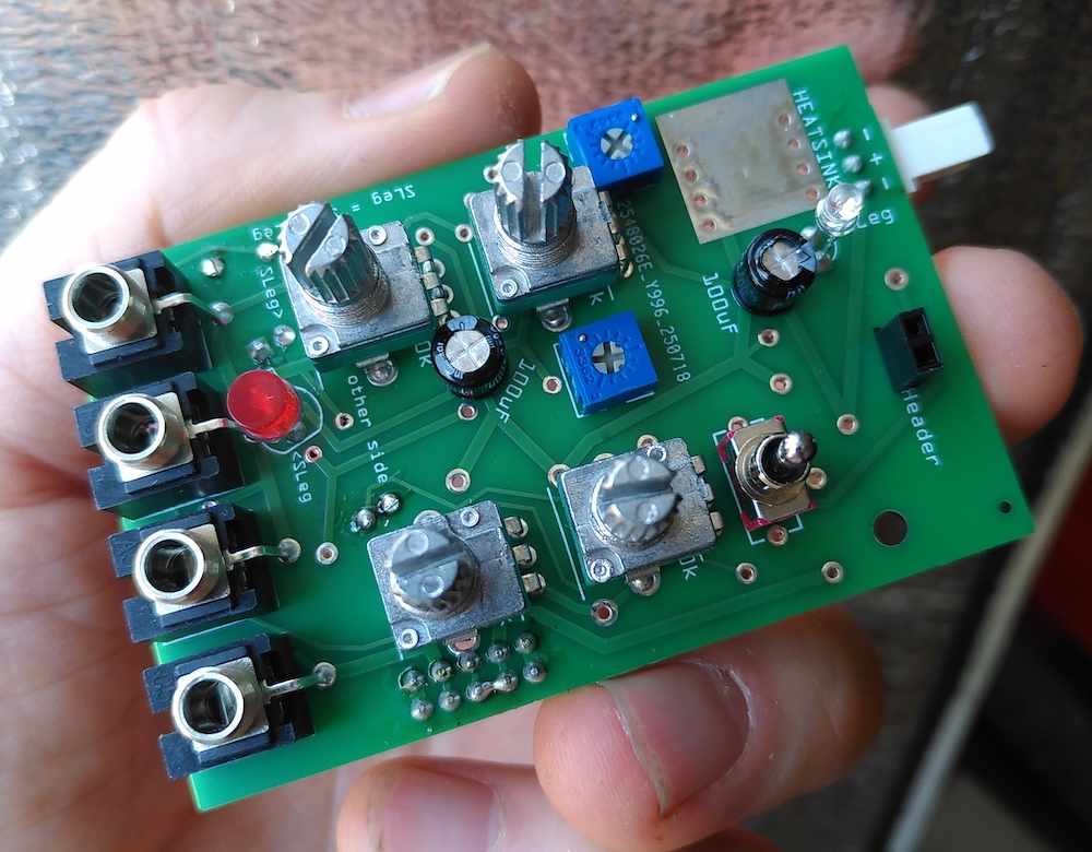
Solder the Capacitors and the Trimmer pots.
Then cut off the small flaps on the front side of the pots and put all components into the PCB, but dont solder them.
Only solder them after you mounted the front pannel. (see also next image before soldering the pots jack and LED's switches.)
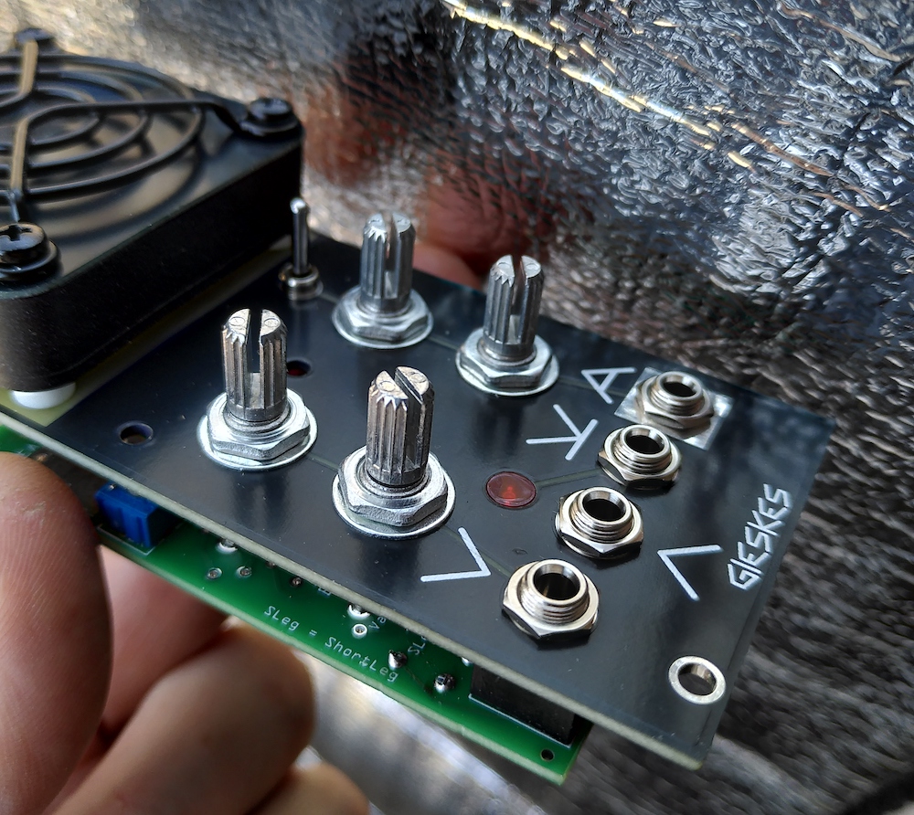
To solder the 5mm LED flat to the top pannel you can put painting tape over the hole for it, and stick the LED to it.
Make sure the 3mm LED is into its hole and the 2 pin header connections are in place.
Now solder it all.