The VCOFan Makes the blades of the fan audible via light and a light sensor, the light reflects of the blades on the sensor (LDR).
The first part contains VCOFan1c instructions, you can follow those and then fill in the gaps with the instructions at the bottom of the page. Basically the VCOFan1d adds 2 pots and 1 inductor.
It is best to read all the instructions before you start.

Put the LDR on the front pannel, make it sort of the height of what i did in the picture.
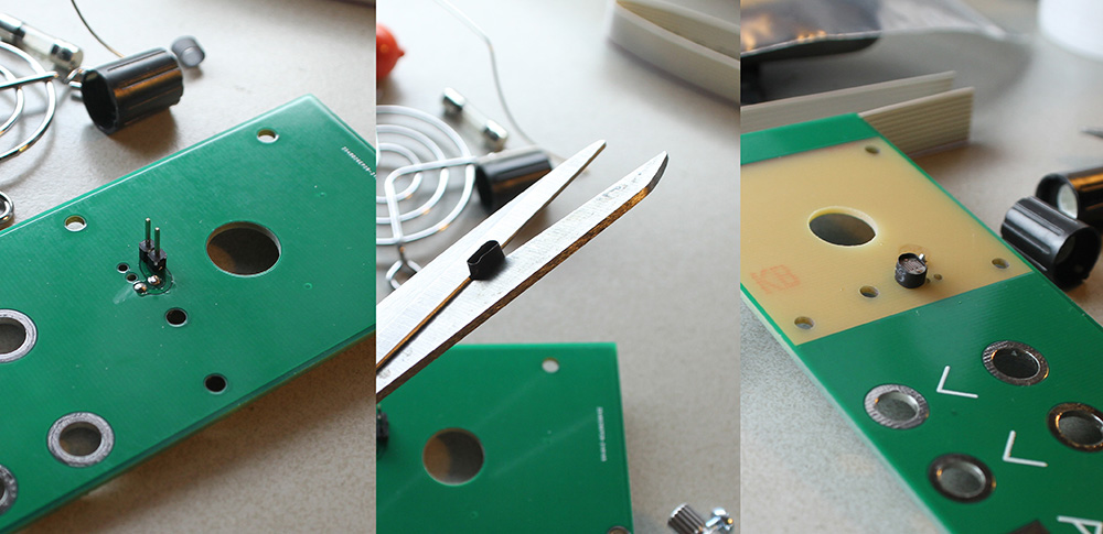
Solder the 2pin header strait up, cut the shringk tube to size if needed, and put it on the LDR. When it is on the LDR you can use your soldering iron to make it shrink around so it wont move anymore.
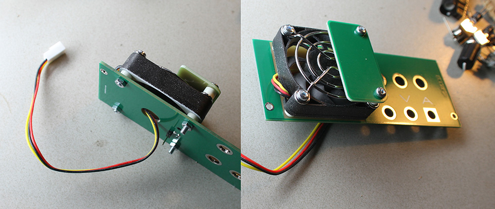
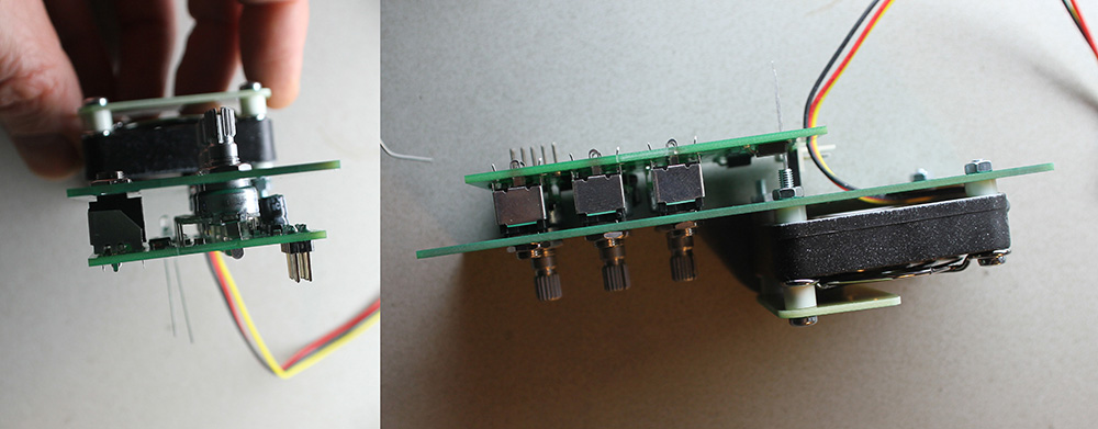
Mount it all like in the above picture.
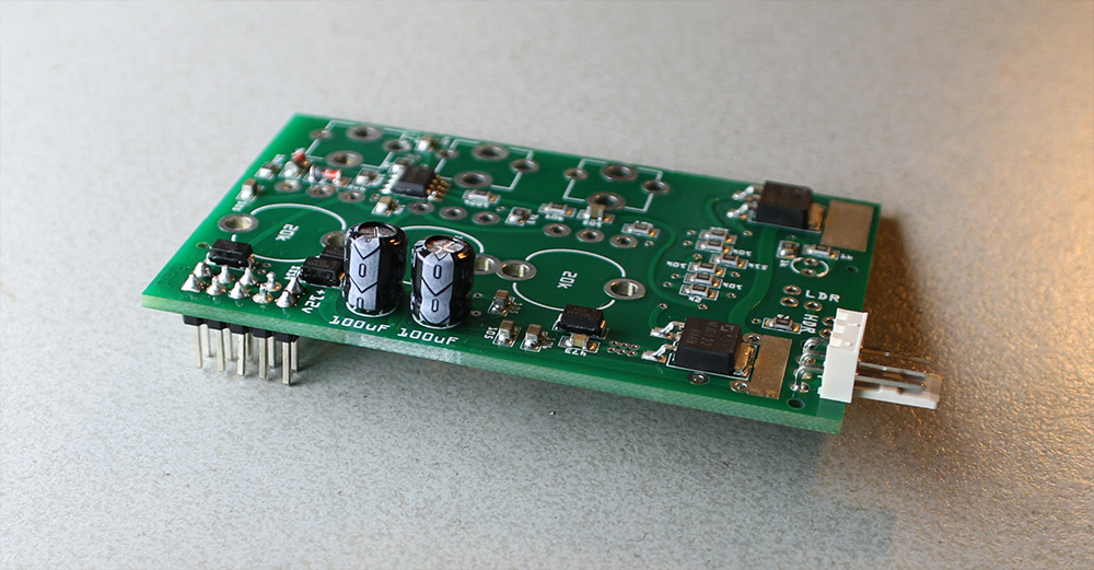
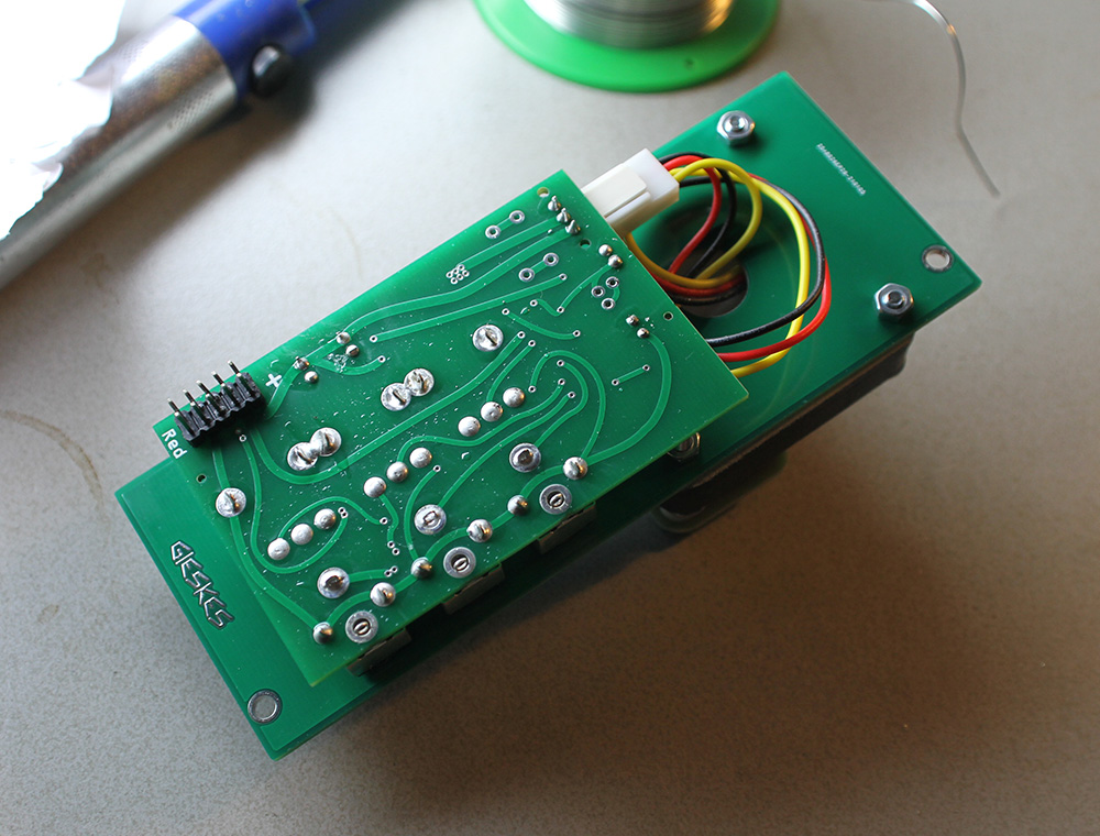
Solder the IDC (2x5 male header), then the 2x 100uF capacitors (they have polarity), and the FAN power connector.
Put the rest of the components in.
The LED has polarity, you can see it by looking at where the short leg is (this side goes to ground).
The 2 pin female header connects the top pannel to the circuit PCB (you can see it next to the FAN power connector).
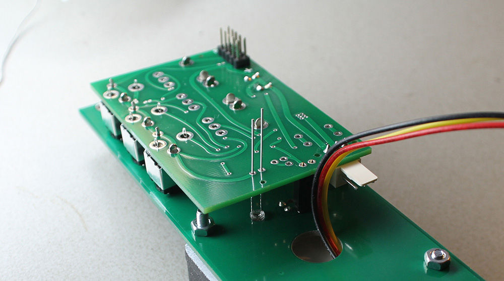
Put in the potmeters and the jack sockets, and screw them all in place.
Check if all it about strait solder, and put on the knobs.
Wind up the fan power cable and `connect it. Then you are done, just the power cable needs to be made. You use a vise to puch the IDC connectors thru the flat cable, look at a eurorack cable you already have and copy it.
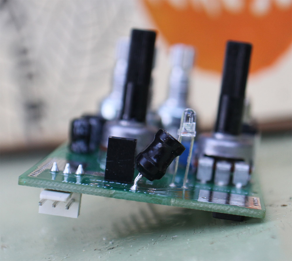
There is one inductor it gives the best sound when you put it in holes market (3) and mounted in a angle.
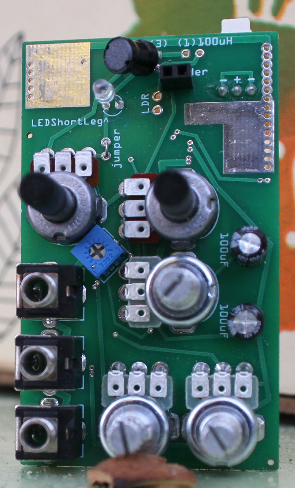
Under the LED there is a silkscreen text that says jumper, you can use a resistor leg connect these two holes.
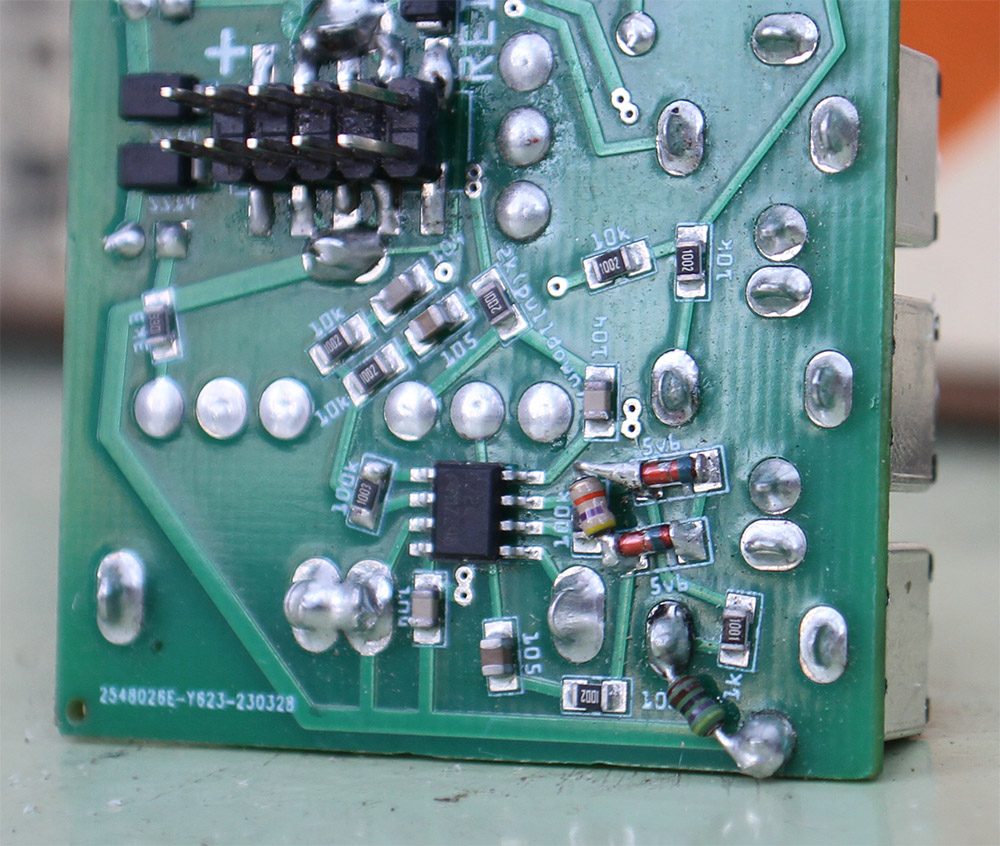
If you want you can add a mod to the VCOFan1d, in the image i bridged the 100k resistor witha 47k resistor, thise reduces the audio volume so there is less limiting via the two 5v6 zener diodes, this gives more controll over the audio volume via the left bottom pot.
I also added a 4k7 resistor from the tip of the audio output jack to ground, this reduces the audio output of the module to give 10v PP, without it fives mostly 12v pp.