Dice2 kit assembling instructions
last update: 16 Apr 2026
Order of Soldering:
- All SMT is already installed.
- Solder the power header.
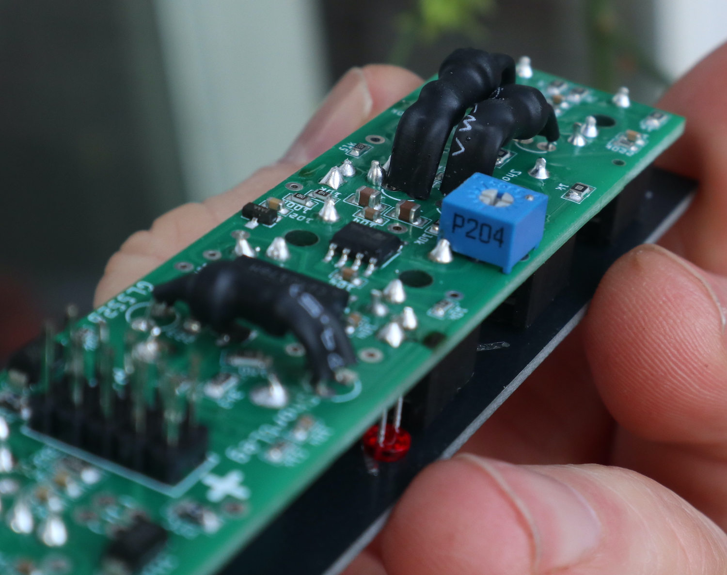
- Vactrols, solder them on the botom side where all the SMT is,
The LED side of the vactrol is smaller then the LDR side and the LED has one leg that is shorter.
There should be a marking on the PCB that says ShortLeg or SLeg with an arrow pointing at the hole the short leg goes into.
- Solder the 2n3904,
- Now the blue trimmer pots, there is one with the value 203 (20k) and one with 204 (200k). The 200k one has no outline marking on the PCB silkscreen (check the images below)
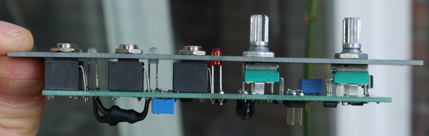
- Put two red LEDS into the PCB and all other components into the PCB and screw it all together with the top pannel. (two of the jacks you will need to cut of one leg to make it fit)
- Make sure its all strait, aligned with the top pannel then solder it.
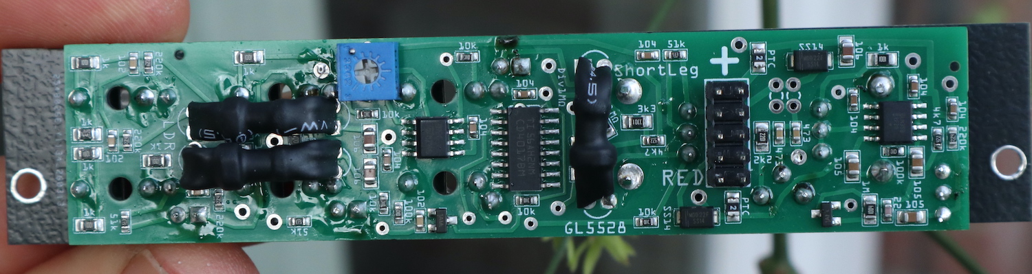
After soldering you can tune the lowpass filter in the circuit, turn the dice pot all the way to the left and turn the trimmer pot till the
LEDs stop blinking. If they keep blinking you can add a extra 473 capacitor over the 473 capacitor for extra capacitance. then see if it works better.