3TrinsRGB+1c Assembling instructions from 2019
Assembling this kit can take a while, but if you follow the instructions it will go fater then if you dont follow them,
even if you are a experienced solderer. This is because some things are unexpected and not as usual.
TIP1: WHEN MOUNTING THE POTMETERS WITH THE NUTS DO NOT TIGHTEN THE NUTS WITH MUCH FORSE, JUST VERY LIGHTLY TIGHTEN THEM, IF YOU USE TO MUCH FORCE
THE POTMETERS CAN ROTATE AND PUT PRESURE ON THE LEGS OF THE POTMETER, THEN WHEN SOLDERING THIS CAN DESTROY YOUR POTMETER.
YOU CAN ALWAYS TIGHTEN THEM A BIT MORE AFTER SOLDERING, IF YOU WANT.
THE TEMEPRATURE RATING FOR THE POTMETERS IS MAX: 280 CELCIUS FOR 3 SECONDS, ESPECIALY THE SMALL LEGS OF THE POTS, TO MAKE YOUR LIFE EASIER
YOU CAN USE LEADED SOLDER ON THE SMALL LEGS OF THE POTS, AND LOWER THE TEMPERATURE TO 260 CELCIUS FOR INSTANCE. IF THERE IS SOMTHING WRONG WITH THE
ASSEMBLY IT IS USUALY THAT A POT BREAKS BECAUSE IT GOT TO HOT.
TIP2: BE VERRY CARFULL WHEN CUTTING OF LEGS OF COMPONENTS, IT IS TEMPTING TO GO FAST.. BUT THEN THERE IS A LARGE CHANCE YOU WILL CUT OF
ONE OF THE SMD COMPONNETS BY ACCIDENT ESPECIALY WITH THOS FLAT BOTTOM CUTTERS, I JUST CUT WITH THEM ON A ANGLE WHEN ASSEMBLING THIS SYNTH.
This is the assembling video (https://www.youtube.com/watch?v=QqKOfuUpSV8) of the previous version of the kit, it is good to watch it also, because the assembling process is pretty much the same,
there is just less components to solder.. (stil it will be allot of work).
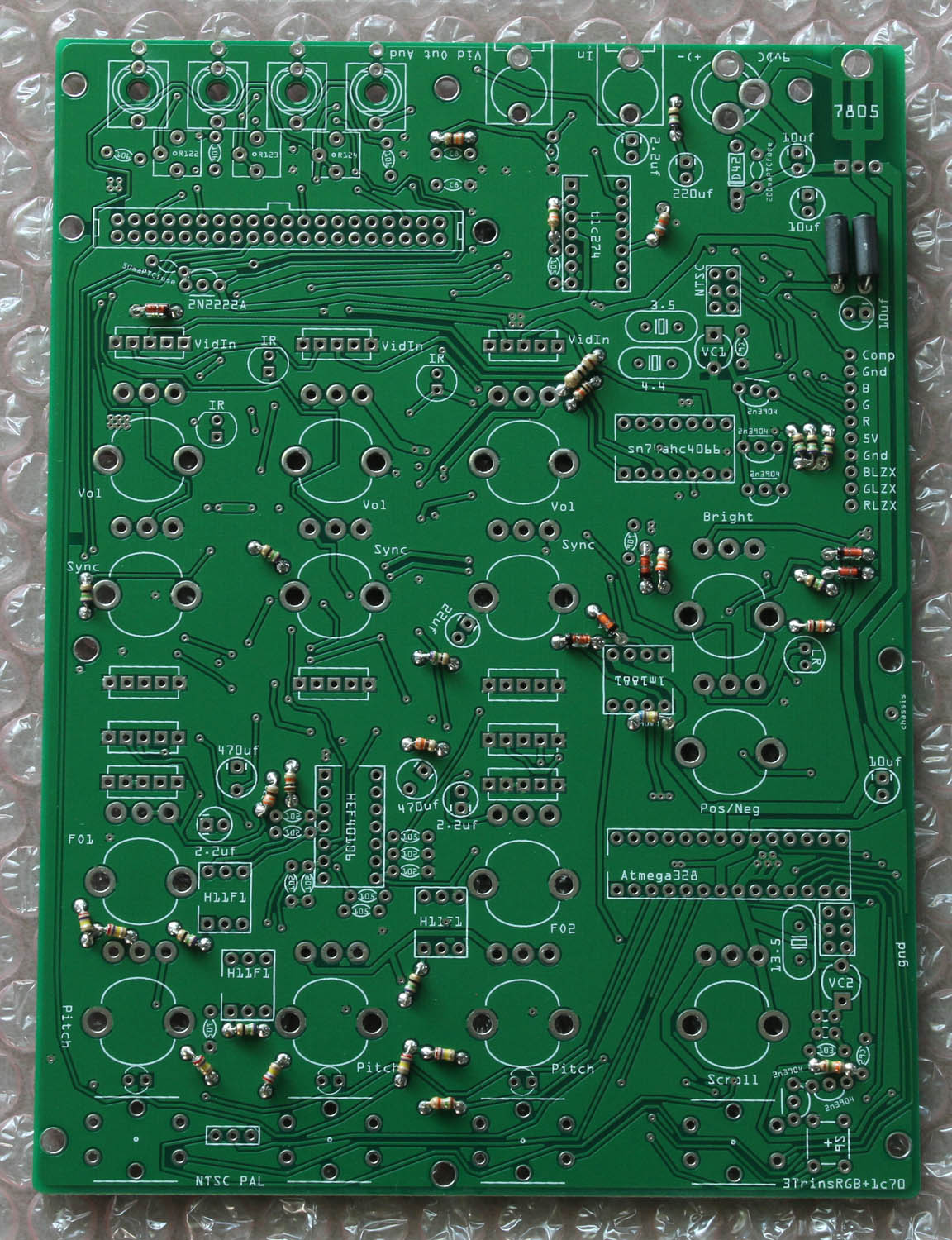
Start with the small components and build up toward bigger ones so you can put the PCB Face down on your table while soldering.
↓ Forward

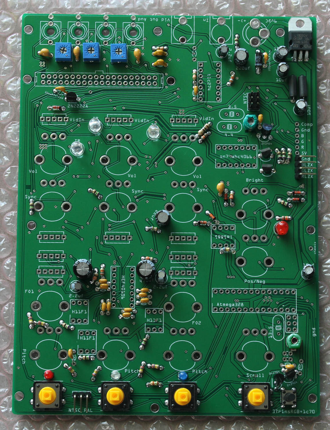
- Add small resistors, they have no polarity, the values are marked on the PCB.
- R42: 15k
- R77: 75ohm
↓ Forward Back ↑
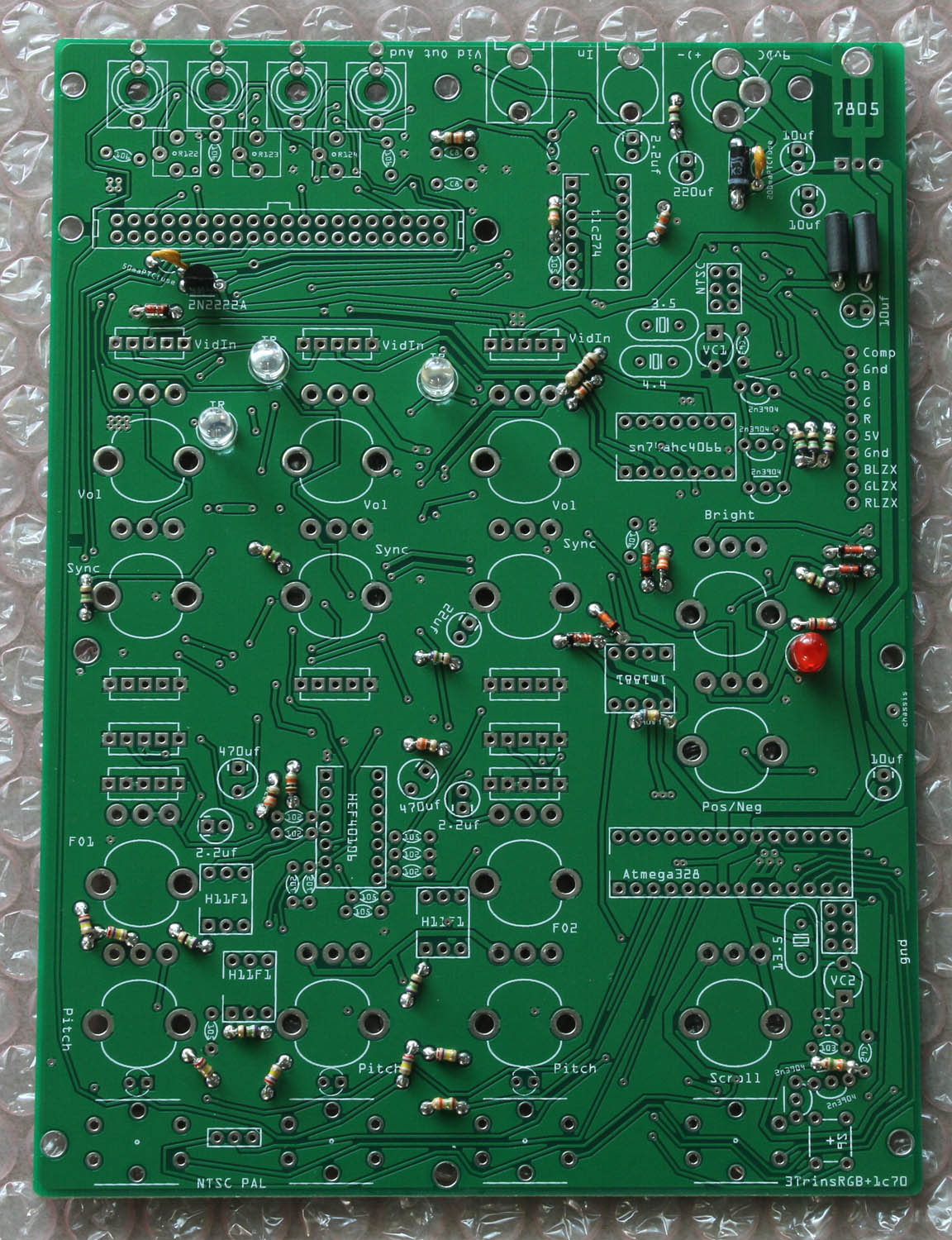
- On the left top there are two black things, they are ferrite beads, no polarity.
- D8: 2 x BAT42 Diodes (on a strip of 2pcs), have polarity.
- D2: 4 x 3V3 Diodes (on a strip of 4pcs), have polarity.
↓ Forward Back ↑
- On the left top there are two black things, they are ferrite beads, no polarity.
- 50maPTCfuse: 1 x 005 PTC fuse, no polarity.
- 200maPTCfuse: 1 x 017 PTC fuse, no polarity.
- 2N2222A: 1 x Transistor, have polarity.
- IR: 3 x 5mm IR LEDs, THE SHORT LEG GOES INTO THE ROUND HOLE FOR LEDS, have polarity.
- 1 x 5mm Red LED, THE SHORT LEG GOES INTO THE ROUND HOLE FOR LEDS, have polarity.
↓ Forward Back ↑
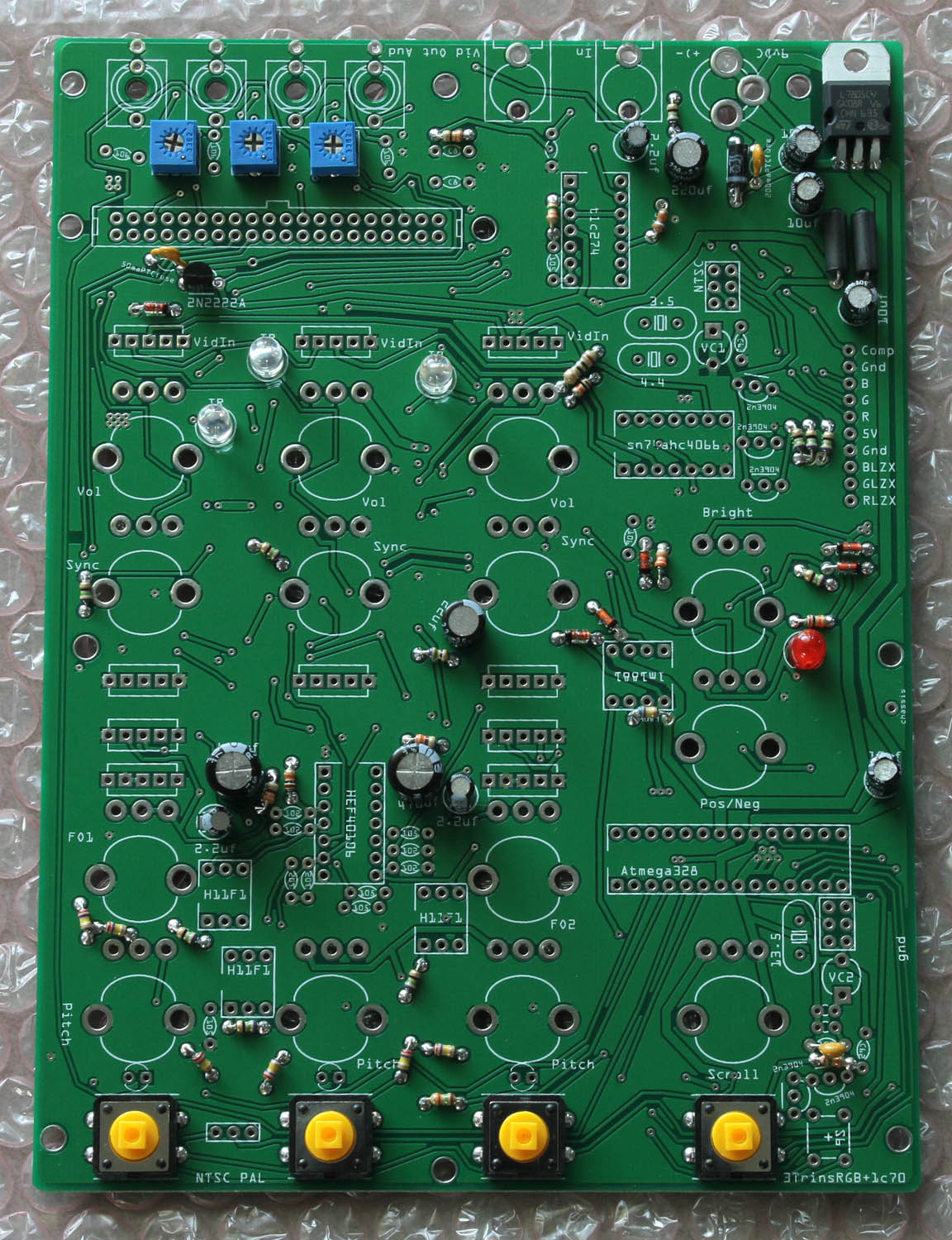
- Black round electrolytic capacitors, the minus is indicated with a square hole with two white lines next to it, have polarity.
- 103: 1 x 10nf (says 103 on part) capacitor, no polarity.
- 3 x 2M Trimmer pots (blue square things), have polarity.
- 4 x 12mm Tactile switches (blue square things with yellow round in middle), no polarity.
- 7805 5Volt Voltage regulator (says L7805CV on part), have polarity.
↓ Forward Back ↑
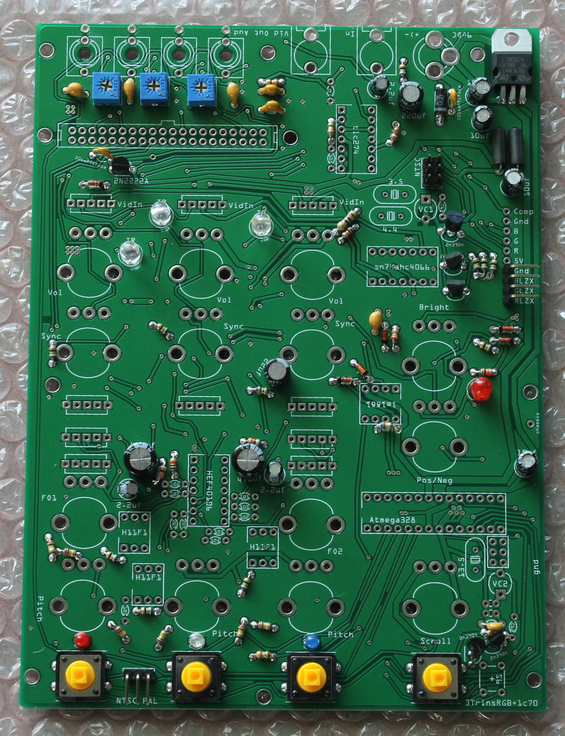
- 106: 4 x 10uF (says 106 on part (color yellow)) ceramic capacitor, no polarity.
- C8: 2 x 2.2nf (says 222 on part (color yellow)) ceramic capacitor, no polarity.
- 2n3904: 5 x 2n3904 transistor, have polarity.
- male headers: 1 x 1x3pins, have polarity.
- male headers: 1 x 1x4pins, have polarity.
- male headers: 1 x 2x3pins, no polarity.
- 1 x 3mm Red LED, THE SHORT LEG GOES INTO THE ROUND HOLE FOR LEDS, have polarity.
- 1 x 3mm Green LED (looks transparent), THE SHORT LEG GOES INTO THE ROUND HOLE FOR LEDS, have polarity.
- 1 x 3mm Blue LED, THE SHORT LEG GOES INTO THE ROUND HOLE FOR LEDS, have polarity.
↓ Forward Back ↑
- C63: 104 (100nf) Capacitor.
- 2 x Green trimmer capacitor (carefully use a file to clean the legs a bit before soldering), flat side in square hole, have polarity
- There is also a Red trimmer capacitor in the kit, i replaced the Red one for a Green one, if you cannot find the green one you can put the Red one into the place under the Atmega328 chip.
↓ Forward Back ↑
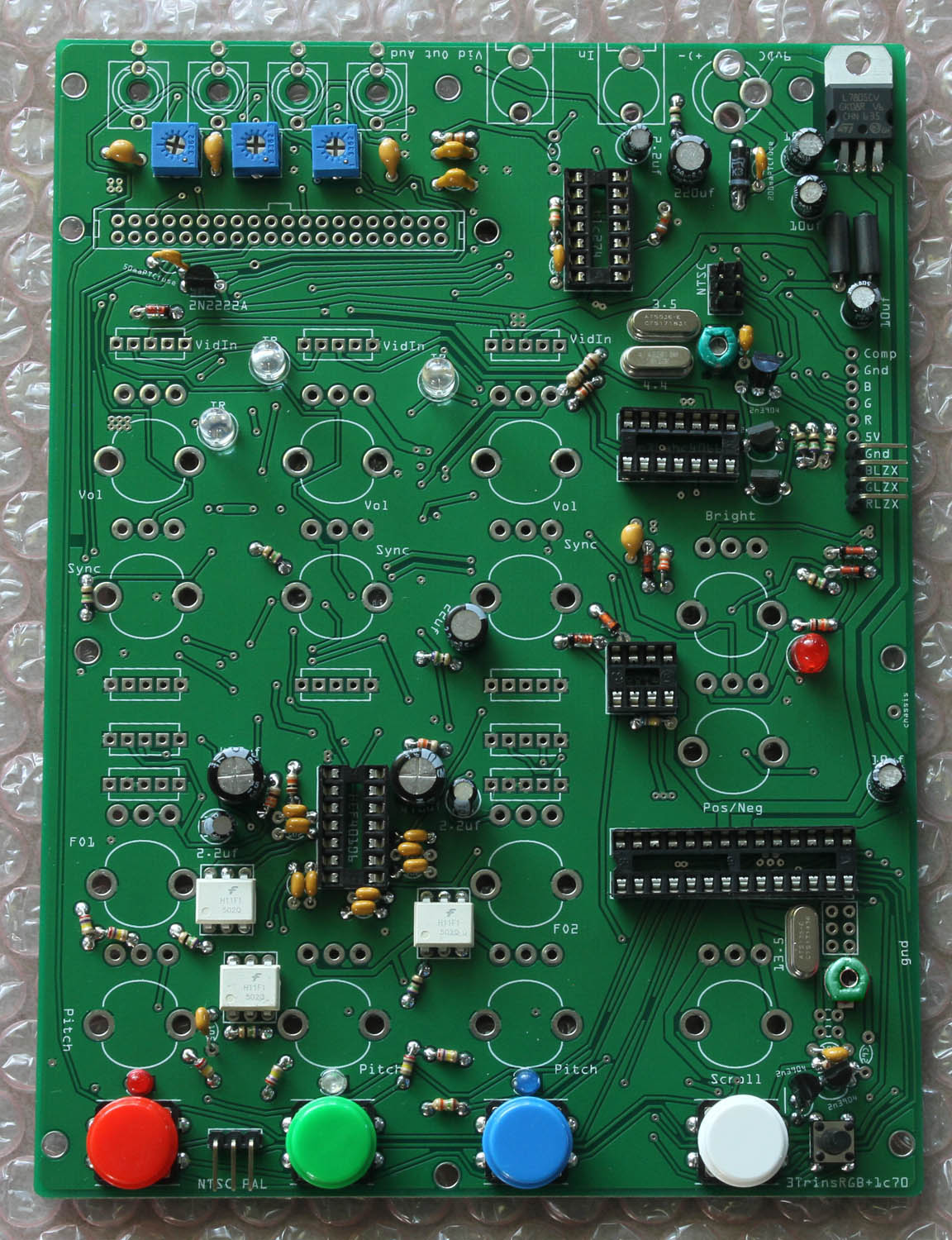
- IC sockets, have polarity
- 3.5 1 x 3.5mhz crystal, no polarity.
- 13.5 1 x 13.5mhz crystal, no polarity.
- 4.4 1 x 4.4mhz crystal, no polarity.
- H11F1 3 x H11F1 optocoupler, have polarity.
- 1 x Red 12mm button cap for tactile switch, no polarity.
- 1 x Green 12mm button cap for tactile switch, no polarity.
- 1 x Blue 12mm button cap for tactile switch, no polarity.
- 1 x White 12mm button cap for tactile switch, no polarity.
- 1 x 6mm tactile switch no polarity.
↓ Forward Back ↑
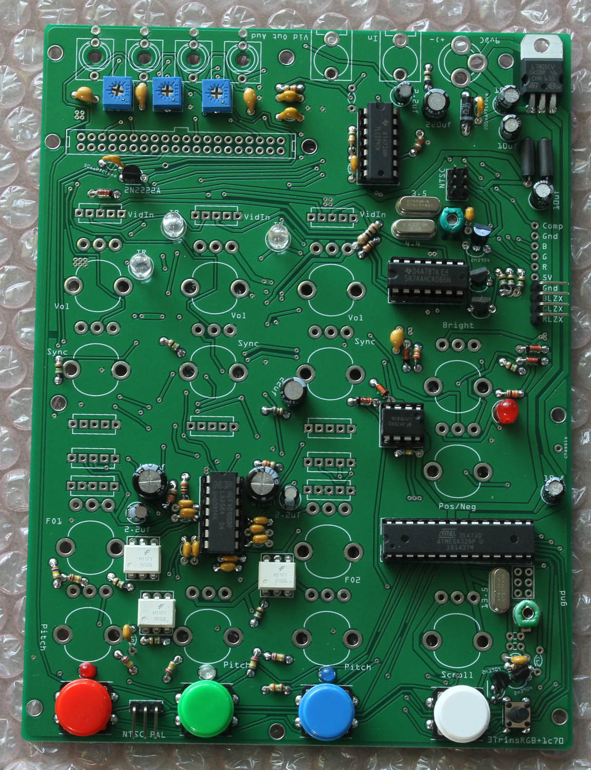
- Plugin all the ICs, make use they are in the correct socket and the polarity is correct.
↓ Forward Back ↑

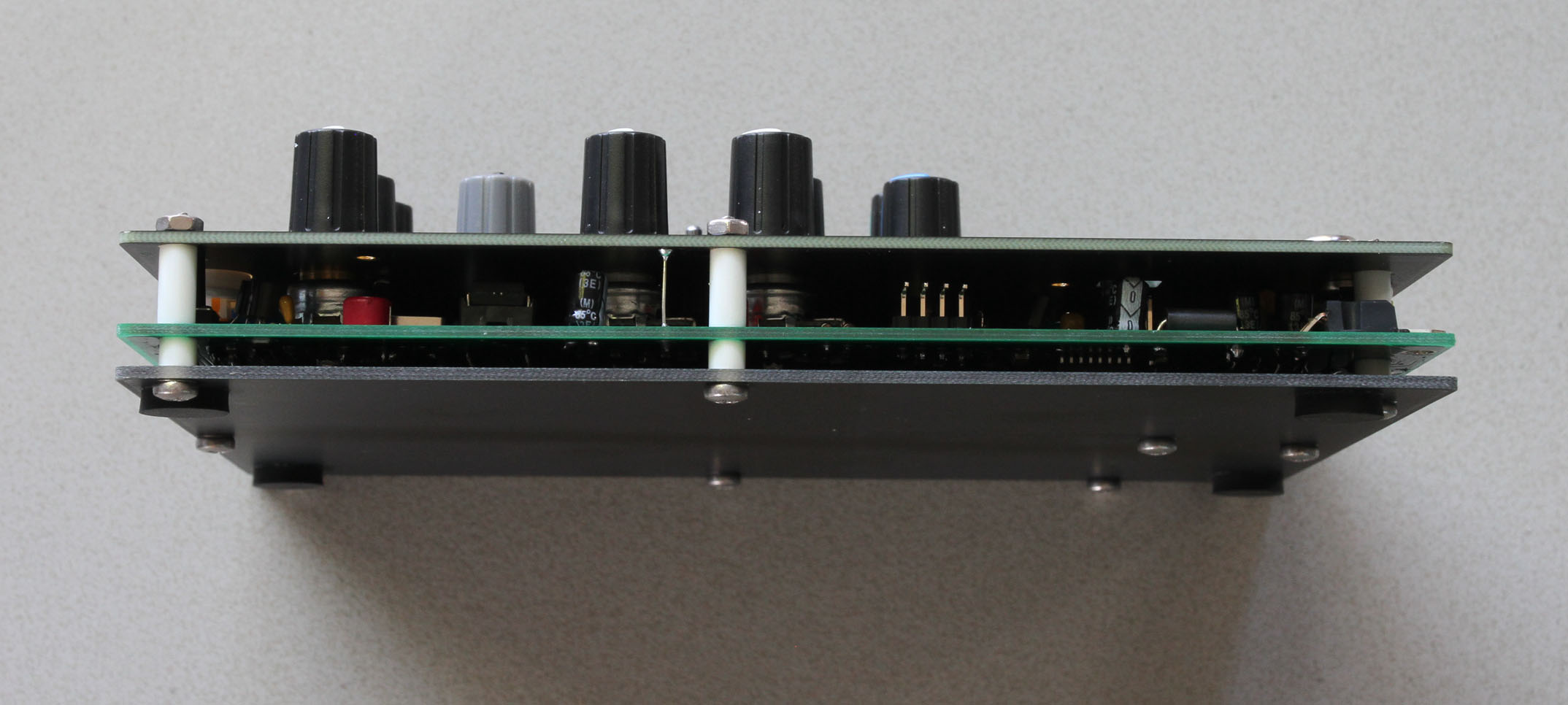
- Put the bolts in from the bottom side and the slide the tall spacers on to them.
↓ Forward Back ↑

- ALL THE COMPONENTS YOU PUT IN NEXT SHOULD NOT BE SOLDERED, THEY WILL BE SOLDERED LATER!
- Scroll the pot above scroll has a different color, it is a 10k potentiometer (says 103 on bottom), cut of or bend the flat of it
so it does not push against the top pannel when it is put on (right bottom pot).
- Put in all the other pots, says 203 on bottom.
- Check the image to see what switch goes where, no polarity.
- Put the spacer PCB (white PCB with 2x20 holes in it) under the gray 2x20 header socket, have polarity.
- Basically put in all the components that are left over.
- When all components are put in, put on the top pannel and mount all the nuts for all the components and bolts.
- When all components are mounted, check if the top pannel aligns straight with the main green PCB and that all is straight.
- Flip over the device with a finger on the gray header socket, otherwise it falls out.
↓ Forward Back ↑

- Tag the gray header on a few points so it stays in, and then you can stop holding it.
- Push the switches down to the green PCB with your finger, otherwise they will slide up.
- Push the yellow RCA composite sockets down to the green PCB with your finger, otherwise they will slide up.
- Solder the rest of the components.
↓ Forward Back ↑
- chassis Solder a leg from a resistor (or a 100k resistor) from the chassis hole to the top panel
↓ Forward Back ↑

- Fill all remaining holes, with solder if you want to clean the PCB with a cleaner (i use thinner),
if you have no clean flux solder you dont have to clean it. BE VERY CARFULL, WHEN YOU CLEAN THE PCB, IF THE THINNER GOES INTO
A POTENTIOMETERIT WILL DESTROY IT.
↓ Forward Back ↑
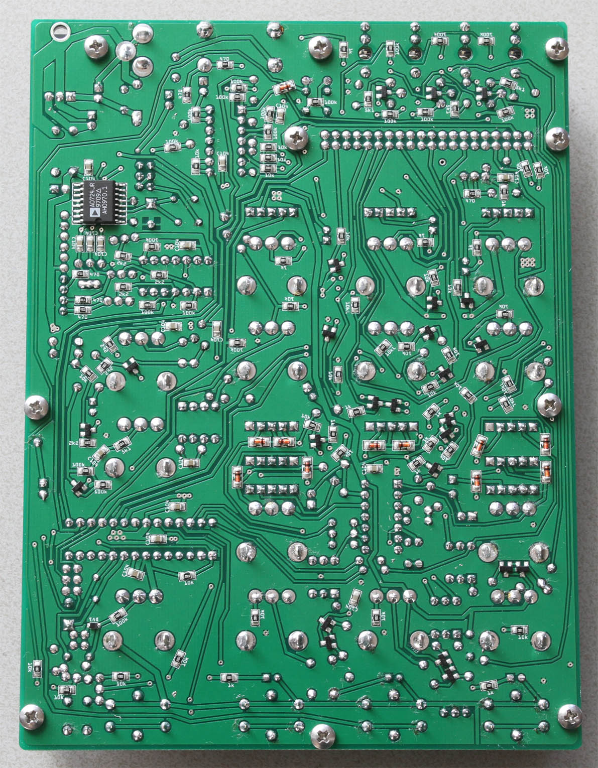
- This is what the circuitboard looks like after cleaning.
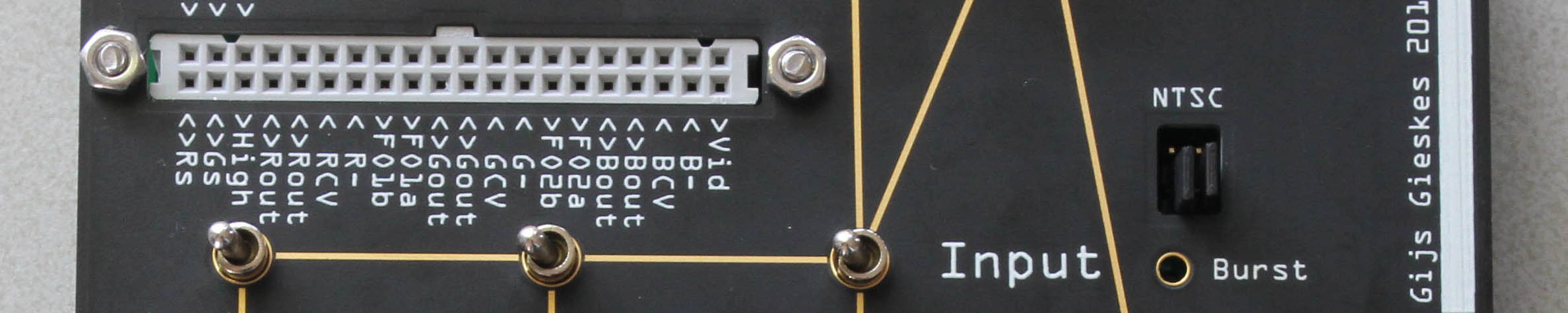
- There are a few jumpers, put the small one on the 1x3 pin male header between the red and green button to select NTSC or PAL.
- Put the long two jumpers on the 2x3 pin male header under the power socket where it says NTSC
on the top pannel.
Connect bottom two pins to the center pins like the image below for PAL, and the top two pins to the center pins for NTSC.
Testing and possibly trouble shooting:
- Measure over the 3 solder points of the 7805 using a multimeter in beep setting.
if there is a long beep that does not stop after a short time there a short circuit some where.
look over the PCB to find it.
- Measure over the DC power socket over the pins that are not connect, if there is no beep its fine,
if there is a beep then it could be that you added to much solder on one of the power socket connector pins
and then the pin is connecting from the other side of the pcb to another pin (to fix this hold the PCB up
above you and put you soldering iron onto the hole now let gravity make the solder go down aways from the
connection).
- If all this is ok now you can connect the synth to your power supply (+ center, 7.5v DC to 12v DC) a TV and to a audio mixer to hear and see if it works.
BE CAREFULL YOU DONT PUT THE SYNTH ON A CONDUCTIVE SURFACE WITHOUT THE BOTTOM PANNEL TO PREVENT SHORT CIRCUITS.
↓ Forward Back ↑
- Take of the bolt nuts (dont remove the nuts of the other components).
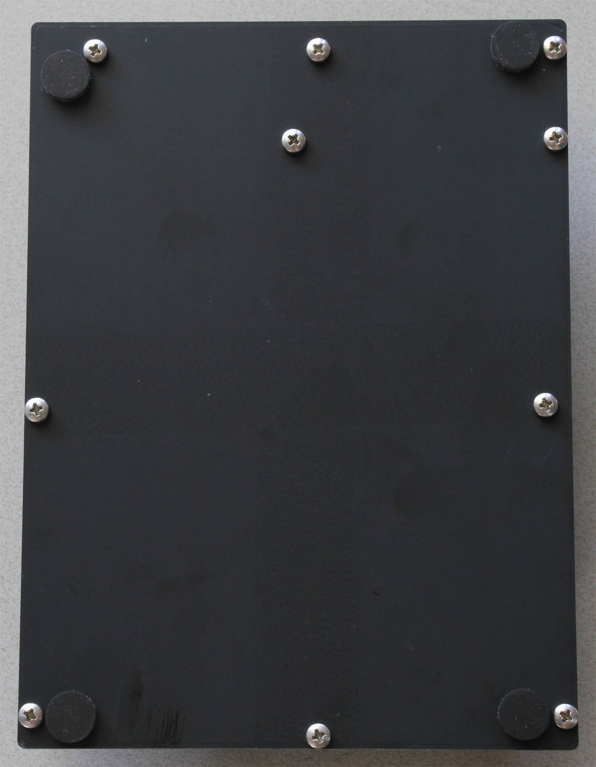
- Put the bolts thru the bottom pannel.
- Put the small 4mm spacers on the bolts.
- Slide the assemebled synth onto the bolts of the bottom pannel.
- Mount the nuts onto the bolts.
- Now your done :-)